How a Power Transmission Tower System Works: From Generation to Grid
Technical Insights · Overhead Power Transmission · ~7 min read
A transmission tower looks simple on a drawing. Some angle steel, a few hundred bolts, a coat of zinc. What decides whether it arrives at a fair price or turns into a problem for the erection crew is everything around it: the voltage, the conductor, the ice sitting on the wire, the soil under the legs, and the way the line is laid out. Get one of those wrong and the tower comes back too light, too heavy, or too late.
1. From the power plant to the wall socket
Electricity leaves a power plant at medium voltage, often 10 to 20 kV. It is stepped up at the plant substation because high voltage moves the same power with less current, and less current means less loss along the conductor. The line that leaves that substation is the one that needs towers.
At the far end, voltage is brought down in stages at receiving substations, and distribution lines take it the last few kilometres to houses and factories. Towers sit in the middle of that chain, and their voltage class is fixed long before anyone draws a single steel member.
Heavy towers, wide right of way, often multi-circuit
750 kV and HVDC
Long trunk routes, few in number
Very heavy towers and special fittings
Higher voltage needs more air between the conductor and the steel, so towers grow in height and in width at the same time. A 132 kV suspension tower is often around 30 m. At 500 kV the same duty is usually 45 to 60 m. Ground clearance rules come from national codes, which is why a 220 kV line in two different countries can come back with two different tower heights.
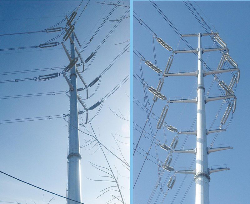
Steel poles on a 220 kV corridor. Height and phase spacing climb with the voltage class.
2. Where the tower price actually comes from
Take two towers of the same voltage, same conductor, same height. Put the first in a 27 m/s wind zone with no ice. Put the second in a 35 m/s zone with 10 mm of ice on the wire. The second one can easily weigh a third more. The shape barely changes. The steel does.
Tension and terminal towers, redundancy in the design
Route and access
Lattice or monopole, and how the tower is sectioned for transport
Soil report
Footing type, stub angle or anchor bolt layout
That is why a usable quotation needs the loading standard and the site data, not just a tonnage. Quoting from a weight figure and a photograph works fine until the foundation drawings come back, or until the tower fails its type test.
3. What each tower does on the line
Suspension towers carry conductors on straight runs, with the insulator strings hanging vertically. Tension towers, also called angle or dead-end towers, hold the conductors under full tension where the line turns. They carry heavier steel and they are the ones that take the broken-wire case seriously. Terminal towers are the last ones before a substation, and the substation designer usually has an opinion about them. Crossing towers, junction towers and transposition towers handle the odd spots on a route.
The mix of duties drives the tonnage of a project more than the voltage does. A line with many turns and a substation at each end carries noticeably more steel than a straight run of the same length. We go through each type in Types of Transmission Towers.
4. Foundations, and why they set the schedule
Tower steel only performs as well as its connection to the ground. Ordinary soil gets pad-and-chimney footings. Soft or waterlogged ground gets piles. Mountain routes often get rock anchors, and low bearing capacity can call for a raft. The stub angles or anchor bolts have to sit exactly where the foundation drawing puts them, because the bottom section of the tower only fits one way. A stub angle cast 20 mm out of position is a problem that shows up weeks later, on site, with the crane already standing there.
If you have a geotechnical report, send it with the enquiry. It costs nothing to share and it is far cheaper than redesigning foundations after the steel has shipped.
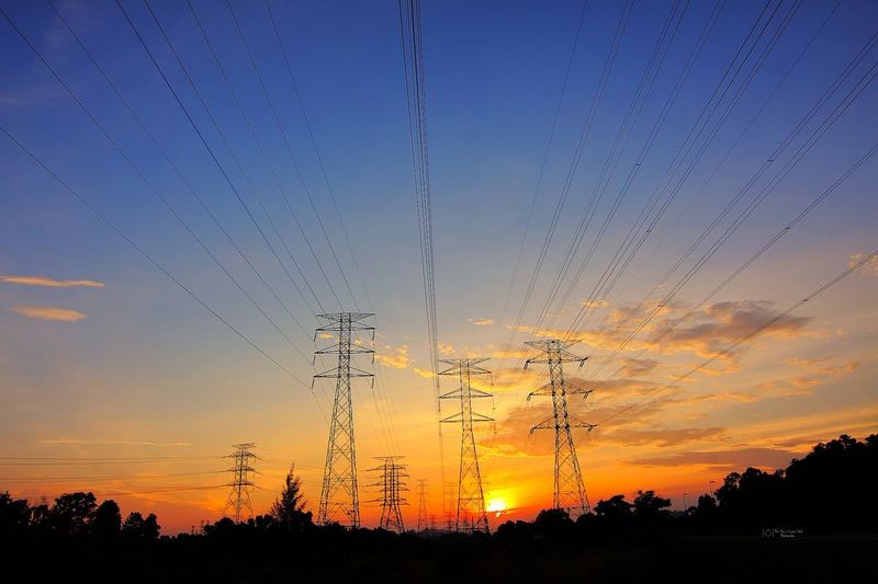
The line ends here. From the terminal towers the conductors run into substation equipment.
5. Steel, galvanizing and bolts
Most angle-steel towers we fabricate use Q235B or Q355B, or their ASTM equivalents A36 and A572 Gr.50 where a project specifies American grades. The designer picks the grade from the loading standard, and we build to the drawing.
Galvanizing matters more than most buyers expect. ISO 1461 asks for roughly 85 µm average coating on steel 6 mm and thicker, and about 70 µm between 3 and 6 mm. ASTM A123 sets the same requirements in mils. On a coastal or industrial site we sometimes quote duplex paint over the zinc. That decision belongs at tender stage, because it changes both the price and the way the galvanizing line is scheduled.
Bolts come in grades such as 4.6, 6.8 and 8.8, galvanized to match the steel. Every tower ships with its own bolt bags and part markings, so the erection crew is not sorting through a mixed container on site. Step bolts, anti-climbing devices and danger plates belong on the drawing, not on a wish list agreed on site.
6. Testing before shipping
For a new tower design, type testing is normally part of the contract. A prototype is assembled in the yard to prove the fit, then loaded in a test station against the cases the line standard requires: maximum wind, ice, and a broken conductor. If a design is going to fail, that is the cheapest place for it to happen.
In production, the checks that protect the buyer are material certificates for every heat of steel, dimensional inspection against the shop drawing before galvanizing, coating thickness and adhesion tests, and a packing check before the container is sealed. On larger export contracts, buyers usually bring in SGS or BV, or send their own engineer to witness the loading test. It is worth asking what is included in a price before comparing two quotations, because not every supplier includes the same steps.
7. What to send us for a quotation
If you can send only two things, send the tower schedule and the loading standard. We can ask about the rest.
Line diagram and voltage class
Tower schedule: types, heights, quantities
Loading conditions, or the wind and ice map of the route
Conductor and OPGW data
Soil report or foundation data, if available
The design standard the line is built to
Galvanizing and bolt grade requirements
Marking and packing instructions
Destination port and Incoterms
If all you have is a single-line diagram, that works too. We will list what is missing and settle it with you before anything is cut.
Worth remembering: the tower is one link in a chain, and the chain sets the price. Voltage fixes the geometry, site loads fix the steel, the soil fixes the base, and packing decides what you pay for freight. Send the system documents and the quotation you get back is one you can build to. Our transmission towers range covers 10 kV to 500 kV.
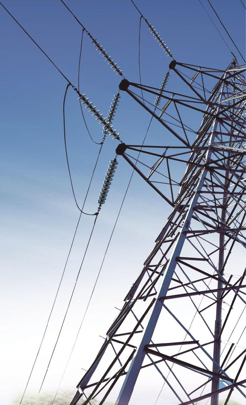
Angle-steel lattice tower built to a customer line design.
Standards & References
Most of our export projects are designed to the following standards:
IEC 60826 — Loading and strength of overhead transmission lines (International Electrotechnical Commission)
ASCE 10-15 — Design of Latticed Steel Transmission Structures (American Society of Civil Engineers)
BS EN 50341 — Overhead electrical lines exceeding AC 1 kV (European standard)
ISO 1461 — Hot dip galvanized coatings on fabricated iron and steel articles
ASTM A123 — Zinc (hot-dip galvanized) coatings on iron and steel products